Things Learned as a Frequent Typist
Alarm Monitor from MQTT, not ADT
When I bought my house it came equipped with one of those olde fashioned house alarm systems where the central panel is wired into the phone landline. I never could quite wrap my head around why an alarm monitoring service, which is essentially just a reverse-telemarketing business, costs so much money to run. They’re paying people next to nothing to make a short phone call but charging customers $50 a month for it. I don’t even have a hard-wired phone so that’s another $25/month on top of that. I had the system so why not modernize it a bit?
The alarm zone circuitry is pretty simple, a wire runs to the sensor which is normally closed and opens when the sensor is triggered. To guard against an intruder simply shorting the wires, an “End of Line” resistor is installed in the panel at the end of every zone’s wire. This gives the alarm system 3 potential voltages
- 0V – Shorted, Alarm
- 12V – Open circuit (sensor is activated), Alarm
- ~5V – Normal
I just needed a way to monitor the zone wire voltages and publish them into my MQTT network. I first considered resistor dividers to drop the voltages down to 0V-3.3V range and then using an ATmega’s ADC to measure them, but I was concerned the extra resistors might change the functionality of the alarm circuit. I just needed to compare the voltage to some reference voltages and give me a simple digital 0 or 1 depending on the alarm voltage.
Analog to Digital Conversion
This clearly called for some Op-Amp action, an area somewhat outside my expertise. I have a drawer full of different things I didn’t understand the difference between at the time I bought them. They’re all little black magic bits in schematics that do something but tend to stump me just how they do it. Because of that, I have never actually used one in a working project before, thus the drawer full of unused components. Reading this article on Op-Amp Ccomparators boosted my confidence as it appeared I could easily create a Window Comparator circuit using [insert nebulous op-amp here].
The article is very comprehensive but there’s an important distinction that wasn’t particularly clear to me when reading the article, that there’s a op-amp comparator circuit and also a device called a comparator which is an op-amp. Comparators made from op-amps turn out to be not well-suited for this task and left me scratching my head when I tried to build the circuit using an LM324 single supply general purpose op-amp. Op-amps and comparators fundamentally differ in their output; op-amps will source current when the non-inverting input is greater than the inverting input. This means the digital output can be up close to the VCC of the device. Bad if we want to read it with a 3.3V microcontroller. Op-amps can be used to create comparators by adding extra components but that started getting complicated.
Comparators on the other hand are open collector output. This means their output is either floating or practically shorted to ground. The output voltage level can be anything you want it to be because you can simply pull up the floating output to the desired voltage. When the inverting input exceeds the non-inverting input, the output will “turn on” and pass current, which will drop the output voltage to practically 0V. I had LM339 quad comparators in my drawer so I was good to go.
Reducing Component Count
Each window comparator requires 2 comparators (one for the high threshold and one for the low threshold). If I combined two comparators to make one digital output, I’d only be able to tell of the zone is “Normal” or in one of the two “Alarm” conditions, but not tell which condition caused the fault. So given 4 alarm zones, that’s 8 comparators and 8 digital inputs on the microcontroller. Rather than go this route I decided to to use just 4 comparators and then toggle the reference voltage by using a transistor to turn on and off a resistor in the circuit. Here, if T1 is off, the reference voltage is formed by the voltage divider 10k/10k or 50% of the input voltage. If T1 is conducting, the voltage divider is 10k/(1k || 10k) or 10k/909 or ~8% of the input voltage.
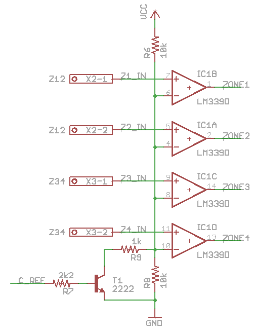
The ZONE outputs are pulled up using the INPUT_PULLUP pin mode of the microcontroller’s digital pins. In retrospect, even T1 and R1 are superfluous. I could just used the microcontroller pin and toggled it between INPUT (no current flows, R9 is out of circuit) and OUTPUT, LOW (pin will sink current and R9 is in circuit).
Getting Data to the Network
Now that I knew how to read the data, I just needed to publish the status of the zones to my network somehow. I already have a Zigbee network, however at $20 per module they aren’t a cheap way to integrate sensors. I also have a 915MHz “jeenode” variant device network, but I’m not as enamored with those RFM12B / RFM69 modules as I used to be. ESP8266 modules on the other hand are fantastically cheap, connect to standard wifi networks, and include both the microcontroller AND the radio in one package for $2.50. They also have libraries for MQTT, making publishing the data into something usable a trivial undertaking.
The ESP modules pull a fair amount of power at 3.3V and typically you see a LM1117 employed. My DC input voltage from the alarm panel is anywhere from 12V-14V, and dropping that down to 3.3V would consume as much as 5W in the regulator. This constitutes a real problem, both in the regulator overheating, and the fact that the panel isn’t rated to source another 0.5A to power my board. Luckily, eBay is also flush with cheap buck converter modules of varying quality. I grabbed a “Mini-360 DC-DC 4.75V-23V to 1V-17V Buck Converter Step Down Power supply” for $0.47/ea.
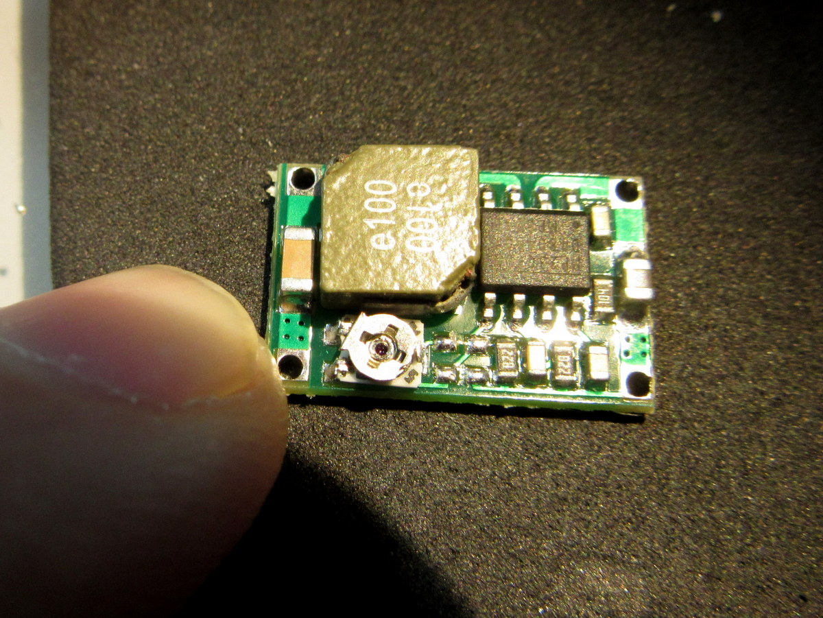
Sidebar – MP2307 Buck Module
Upon receiving the power supply modules, I was disappointed to note that I could not get them to generate 3.3V no matter what I set the adjustment potentiometer to. Looking at it more closely, I discovered that the pot is mounted too close to the inductor which prevents the screw from turning to the point where 3.3V output would be. Also note that the screw itself can short against the inductor’s body, which is not a problem in this design because the inductor output is actually connected to the wiper via the PCB as well. The lowest this module can go is around 6V.
Looking at the MP2307 datasheet, I see the output voltage is Vout = 0.925 * (R1 + R2) / R2. The installed pot is 160k and R2 is the first 0603 resistor to the right of that which is labeled 822 or 8.2k. I need the pot to adjust to ~19.5k ohms in the current configuration, which I physically can not reach due to the clearance issue. There are several ways this module can be modded to allow 3.3V output.
- Desolder the adjustment potentiometer and scoot it away from the inductor to allow adjusting down to lower resistance. I did this first but the precision of adjustment is pretty coarse– 3/4 of a twist can adjust between 20.5V and 0.925V. The difference between 3V and 4V is just 13 degrees of rotation.
- Remove the potentiometer and 8.2k R2 and make the output fixed using the datasheet values of R1=26.1k R2=10k. Conveniently, the PCB designer has given us pads to do this. The first set of 0603 pads to the right of the pot are designed for this purpose, or even the left two pads of the pot placement itself can be used with an 0805-sized resistor. I probably would have done this but I didn’t have a 26.1k resistor on hand.
- Place resistors in parallel with the pot or R2 resistor to change their values. The math behind this was too complicated for me.
- Remove the R2 resistor and replace it with a value to increase precision around our desired output. Given I can adjust the pot between ~80k-160k, I plugged some E6 series resistor values into the formula and found R2=33k gives me 3.167V to 5.410V. Perfect for 3.3V or 5.0V use and quick 2 minute mod.
I’ve made a quick Google Docs Sheet for calculating output voltages given R1 and R2 ranges.
Software
There are plenty of great libraries for connecting ESP8266 modules to wifi networks and creating web servers and MQTT clients, so for once it seemed like overkill to roll my own framework. I picked the new Homie framework, which contains a provisioning system for initial configuration, MQTT support, and a flexible OTA upgrade system. My entire codebase was 166 lines of code, with only 7 lines needed for boilerplate.

Production
Ship the design off to OSHPark and $10.50 later I had my boards. Programming them was a bit of a challenge. My !RESET and !FLASH lines being controlled by just one DTR line just wasn’t working, and the DTR line was being held low after flash so it wouldn’t boot (this took me a couple hours to figure out). I eventually just cut the trace and abandoned the idea of getting it working. To flash I just needed to compile, plug in the FTDI USB end, hold the flash button on my device, then plug the FTDI cable into the device and release the flash button. Then I could flash the initial firmware. After that, I can just use the Homie OTA process to install new firmware as needed.

Prototype to production with OSHPark!
Cost
- PCB – $3.50
- ESP-12 Module – $2.50
- Voltage regulator – $0.47
- LM339 SO-14 – $0.25
- 3.5mm Screw terminals – $0.29
- SMD button – $0.06
- Misc passives (resistors/capacitors) – ~$0.20
- TOTAL: $7.27
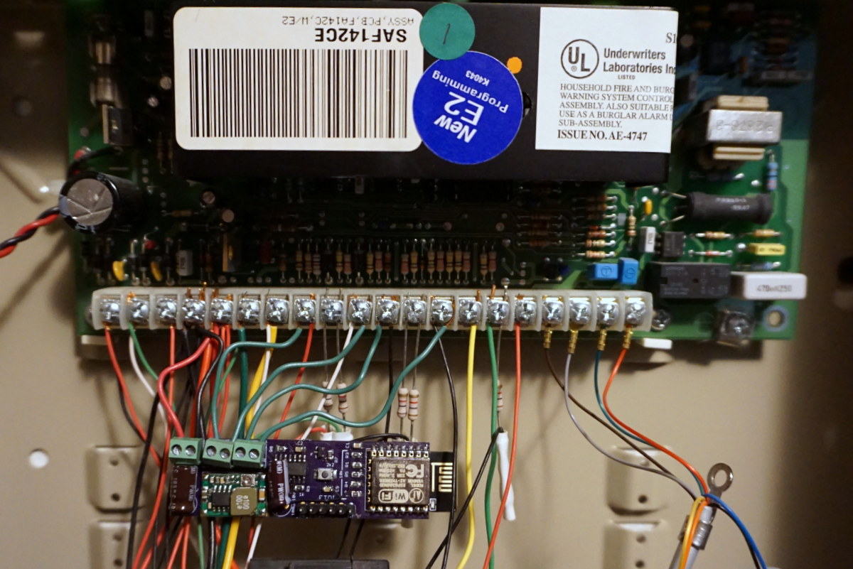
Just wire it to the panel with some solid wires and let it dangle like the rest of the crap in there.
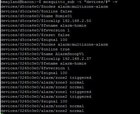
Once the data is in MQTT, do with it as you wish!
Source code and schematics are available on GitHub
https://github.com/CapnBry/AlarmHomie
Comments are closed.