When AREF isn’t AREF (yet)
I’d often noticed that measuring analog inputs on my ATmega, that the first round of values usually differed substantially from subsequent values. The datasheet even warns of a similiar-sounding issue:
The first ADC conversion result after switching reference voltage source may be inaccurate, and the user is advised to discard this result.
Knowing that the Arduino libraries don’t actually set the reference voltage until the time the first sample is made, it seemed logical that these first samples were an artifact of the voltage changing. However, it wasn’t just the first sample, or the first couple samples. It could take dozens of samples before the value returned had stabilized (i.e. stopped increasing by more than 2 LSB). Being a boot-only issue. I was content to ignore it until I started trying to read the on-chip temperature sensor.
You don’t hear a lot about it but ATmegas have an on-chip temperature sensor connected to their ADC MUX. It can only be read if the analog reference is set to use the 1.1V internal voltage reference. All my other analog inputs needed to be referenced to the 3.3V AVCC, so my code needed to switch back and forth. Easy enough to switch to the internal reference and link the ADCMUX to the temperature sensor, which is ADC8
// Switch to ADC8 and analog reference INTERNAL
ADMUX = (INTERNAL << 6) | 8;
The problem of the first N reads now being inaccurate was now being realized on every cycle. This phenomenon finally warranted investigation.
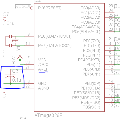
When the ATmega is running on DEFAULT (AVCC) or INTERNAL voltage reference, the AREF pin is connected to these sources so it may therefore be decoupled by an external capacitor to improve noise immunity. This is the sort of thing you see in many schematics.
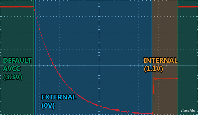
Adding capacitance to this pin means from switching from the 3.3V of AVCC to the 1.1V of the internal reference is no longer a nearly instantaneous switch. Here's a scope graph of switching from DEFAULT at 3.3V to EXTERNAL (which has no source attached) to INTERNAL (1.1V) and back to DEFAULT. Given 2.5ms divisions it takes over 10ms to decay down to near-0V and at least 2.5ms to go from DEFAULT to INTERNAL.
Given that we know the capacitor is 0.1uF and the starting voltage is 3.3V, if we count the time it takes to lose 63% of its charge (down to 1.221V) we can calculate the internal resistance of the the AVR and therefore predict the amount of time it takes to switch from 3.3V to 1.1V directly. In this case it takes 3.353ms
3.353ms = R * 0.1uF
3.353x10⁻³s / 1.0x10-7 = R
R = 33530 ohms

From the equation V = V0 * e ^ (-t/RC)
t = -1n(V/V0) * RC
t = -ln(1.1/3.3) * 33530 * 1.0x10-7
t = 3.68x10-3 = 3.68ms
This is fairly unacceptable for my application considering I wanted the whole operation to be completed in a lot less time than that. Lowering the AREF capacitor would proportionally lower the discharge time
0.1uF = 3.68ms
10nF = 368us
1nF = 36.8us
It is important to note that this is also the same effect I was seeing on boot up. When you first start the ATmega the reference is set to EXTERNAL so there is 0V on the AREF pin. Arduino libraries will switch the reference to DEFAULT on your first analogRead() call unless you explicitly change it using analogReference(). The AREF capacitor now must charge to AVCC before you can take an accurate reading. Fortunately the resistance between the two is very small so it charges on the order of nanoseconds. Still, there can be a small difference in your ADC reads until the capacitor charges.
Back to the task at hand, measuring the on-chip temperature sensor:
unsigned int getAvrTemp(void)
{
    unsigned char high, low;
    ADMUX = (INTERNAL << 6) | 8;
    // delay goes here if need
    ADCSRA |= bit(ADSC);
    while (ADCSRA & bit(ADSC));
    low = ADCL;
    high = ADCH;
    return (high << 8) | low;
}
“Due to process variation” the value you get back is initially worthless. Both the internal reference voltage and the temperature circuit have some amount of tolerance and temperature variation coefficients. For example the “Typical Case” unit should read 314mV at 25C and 380mV at 85C. My device read 373mV indicating my living room was about 78C. To get accurate values you must store some calibration data specific to your ATmega unit. For more information on calibration see Calibration of the AVR's internal temperature reference
Comments are closed.

