Grill Control Project Part 3
Hardware construction time. Note: this is for the v3 version of the HeaterMeter controller.
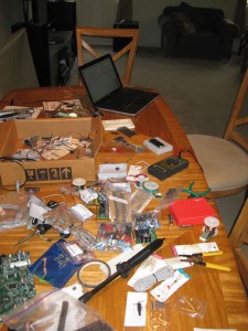
I ordered the Arduino Duemilanove and buttons from SparkFun, the WiShield 2.0 from AsyncLabs, and the components and blower from DigiKey. What you end up with is a whole dining room table full of parts.
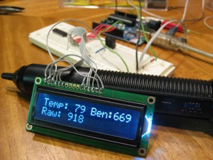
First thing I wanted to do was to make sure the Serial LCD concept was going to work. This seemed natural because everyone wants to see something working; where’s the glory in building a system that has no outputs? Without the LCD, HeaterMeter would suffer the same fate as Schrödinger’s cat. Breadboarding was used extensively throughout the build process, which is a good thing considering I kept wiring up things half backward. Remember, IC pin numbering goes in a U shape from pin 1 on the upper left, down to let’s say 7 on the left, then straight across would be 8 and then up to 14. I know this yet I kept wiring the right side inverted. Stupid right side.
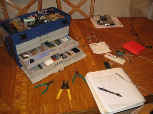
I spent a lot of time on the breadboarding trying to work out some hardware issues. The temperature probes are designed such that there’s one wire inside them and the metal on the outside is the other conductor. This was giving me all sorts of erratic measurements if two of probe wires came in contact with each other. I tried numerous things to prevent this but was never 100% successful in isolating the two circuits. I finally gave up and went with using the outside as ground because it gave better results and figured I’d come back and revisit the problem after I had a working device. Bob’s design used the shield as ground, and the Maverick digital thermometer I stole the probes from also used shield as ground, so I assumed that was the best design. Looking back at this from the future I can say there does not appear to be this issue at all in the final device. I also took some time to get organized.
Once I was relatively certain the key subsystems were working properly I needed to move to board layout. The free version of Eagle allows you to do board layouts too, as long as you don’t try to drop a component outside the free version design space square. I needed compactness to fit inside the project box I had bought, so things needed to be tight without getting too complex because I am an amateur solderer working on cheap Radio Shack perfboard. Here’s my design, but note there are no inputs here. I ran the inputs along the top of the board in the final design.
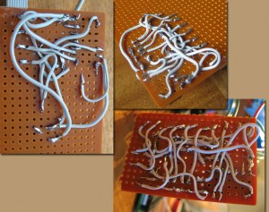
Then came the soldering. I used strips of wire from an old 40pin IDE cable, which are small stranded wires, but even with these small wires the underside became a mess. Since then I’ve heard the suggestion to use teflon insulator or “POLYTHERMALEZEtm” 30AWG wire, which is smaller solid core wire that should be easier to work with. When I build the next version of HeaterMeter, I will use that wire and probably wirewrap most of the connections. Building this was like a nightmare with cutting just the right length wires then soldering without making a complete mess or wiring something backward because I flipped it upside down.
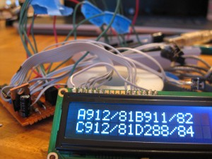
Luckily, I only swapped two connections throughout the whole construction so I didn’t have to spend much time debugging. I had the LCD contrast pot hooked up such than when you turned the contrast all the way down it would be a short to ground and the whole device would power off. Thank goodness the Arduino has a fuse in it to prevent me from blowing my USB port. Here we are reading the 4 temperature probes.
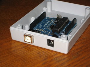
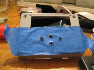
Physical construction was my next hurtle– trying to keep things as professional as possible and not just stuffing everything into a shoebox.
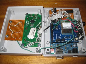
Everything fit inside like a glove. I had intended the LCD to go across the short dimension but it didn’t fit and the project box was like $10 so I wasn’t going to throw it away. It isn’t objectionable in this configuration though.
The parts you’re seeing from left to right are: button control board, LCD, Arduino w/ WiFi stack, and my circuit above that.
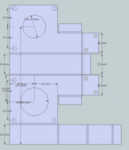
The pit blower fan would also need a mechanism for holding it to the grill. I designed a simple box in Google Sketchup that I prototyped in cardboard. I originally imagined it as cut from sheet metal but that’s hard so I’m still using the cardboard mockup at this time. It is showing some wear but hasn’t caught fire or anything. I connected the fan to HeaterMeter using an old RCA composite video cable.
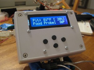
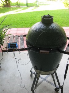
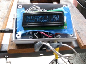
Here’s what the whole thing looks like in operation. The photos are from an early “Burn Test” from before the case was completed, buttons were built, and WiFi card ordered.
You may have noticed there is software on the device. I haven’t covered that yet but it deserves its own post.
Comments are closed.
