Grill Control Project Part 2
Based on Bob’s lead, I chose the Arduino platform as my microcontroller. Specifically the Arduino Duemilanove.
- ATmel ATmega168 Micocontroller
- RISC 8-bit CPU running at 16MHz / 5V
- 32kB code space (30,720 bytes usable)
- 2kB RAM
- 1kB Flash storage EEPROM
- Integrated ADC, Digital PWM, SPI bus interface, UART TTL Serial
- C/C++ programming environment
Yeah 2kB of RAM. For comparison, my blog front page is currently 250 times that. 30kB of usable code space? The default Delphi Project1.exe baseline with no user code is 13 times as large. Squeezing everything in to that space seems like a challenge: a web server, LCD and buttons with a menuing system, and I reckon it should control a grill too.
This post was going to be about the platform, but that’s boring. Let’s just jump into the project and I’ll introduce things as needed.
Designing HeaterMeter
Usually the first step of any software design project is coming up with the project name. You can prove this theory by going into Visual Studio and selecting File | New | Project. BAM. It is prompting you for the name. Nothing says “Version 1.0” like just accepting the default name of “Project1”. Consider using something edgy that shows a lot of time went into development, like “Project10” or something. Using numbers to name everything seems convenient, but can really get confusing if you use this method to name everything you create, or pets you own. As luck would have it, this article is being written after the device has already been built, so we have the luxury of already having the project named by a friend of mine. The project will be called HeaterMeter, or HeMe, or just “that grill control thing I’ve spent 100 hours on”.
I wasn’t sure I was up for completing this project, so I belayed the ordering of the WiFi card (WiShield 2.0), by far the most expensive component, until I had a working prototype. Knowing I’d probably be using it there were certain design changes from Bob’s design.
Bob used the original WiShield 1.0. The 2.0 adds a 16Mbit dataflash chip to the design, which is accessible by the SPI bus. The idea is that dataflash allows you to serve some static content web pages or store log data in a non-volatile area. That’s actually a good thing, considering the diminutive size of the program space available on the Arduino. The WiFi card itself already uses a large number of digital pins, and this 2.0 version adds another:
- 1 WiFi LED. Indicates the WiFi is connected, but can be disabled
- 1 Interrupt line. One digital line is used as an interrupt. The Arduino can watch this line and call an Interrupt Service Routine (ISR) in your code when it changes, just like a regular operating system does.
- 1 SPI Clock
- 2 SPI Data lines, called Master In Slave Out (MISO) and Master Out Slave In (MOSI)
- 2 SPI Slave Select, this is an active-low line that indicates what device on the SPI bus you’re talking to. The WiFi needs one and the dataflash on the shield needs one too.
In addition to those used by the wireless, the Arduino itself and our HeaterMeter parts need lines too.
- 2 for Arduino serial Rx/Tx. The Arduino talks and is programmed over serial (or in the case of the Duemilanove, a FTDI USB to Serial) so these should remain unused by our application.
- 4 LCD Data (D0-D3). The LCD uses a Hitachi HD44780 parallel interface, which can receive a whole 8 bits at a time but Bob’s design uses the 4 bit mode, which shifts data in a nibble at a time
- 1 LCD Register Select (RS). When this is low, the LCD interprets data as commands. When it is high, it interprets it as character data
- 1 LCD Enable (E). I prefer to call this EXECUTE because when you set this pin, the LCD acts on the data currently on the other pins. This allows you to set the data and RS pins individually with each intermediate state not making your LCD all wonky in between.
- 1 pin for the HeaterMeter PWM fan output.
- At least 2 digital pins for button inputs to adjust the temerature
Sweet, so 18 digital I/O pins and the Arduino has 14 so we’re all se… crap.
Slimming the LCD
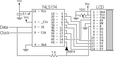
Aside from the entire WiFi shield, the next largest consumer of digial I/O lines is the Hitachi HD44780 parallel LCD controller. Because the LCD doesn’t care what the value of the data and RS lines are until the E line is toggled, we can use this to our advantage by shifting the data in one bit at a time. To perform this, I chose an 74LS164 parallel shift register based on this ingenious 2-wire method. The clever bit is that he uses a resistor and a diode to form an AND gate that allows you to use the data line as both data and E. Even better, someone else had also written the C++ class for the Arduino.
ZOMG Buttonz
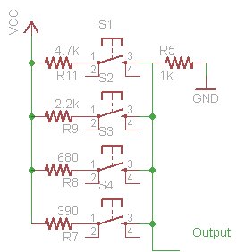
The first thing we can do use the analog ADCs for reading the button input. On the Arduino, the 6 analog inputs can actually be used for digital I/O as well, but I’ll need at least two of those for reading temperature probes. Already I was considering expandability. What if I wanted add more temperature probes, or more buttons? I’d hate to paint myself into that corner. I decided to use a bunch of buttons with resistors to form a voltage divider and read N buttons from one analog input. I spent a good amount of time in the java circuit simulator screwing around with different resistor values, trying to find a good combination of values that allowed me to detect if two buttons are pressed at the same time. That lasted for about an hour until I gave up and decided that with four buttons I wouldn’t need to define button chords. Another principle of development is that if at first you don’t succeed change the rules.
Final Digital I/O Layout
With the LCD converted from six to two wire and the buttons moved to an analog circuit, we actually have two pins spare. I’ve arranged them such that they are Pulse Width Modulation (PWM) control pins to that they may be used to control a second and third blower if the system is to be expanded to support multiple grills in the future. Here’s the final digital pin layout.
D00 - Rx
D01 - Tx
D02 - WiFi Int
D03 (PWM) - Blower
D04 - LCD Clk
D05 (PWM) -
D06 (PWM) -
D07 - SS for flash
D08 - LCD Data/Enable
D09 (PWM) - WiFi LED
D10 (PWM) - SS for WiFi
D11 (PWM) - SPI MOSI
D12 - SPI MISO
D13 - SPI CLK
Silence the Blower
The basic operating principle of HeaterMeter to vary the speed of a fan to provide air for combustion in the grill. When the fan is off there should be little to no air getting into the grill and the fire starts to go out. To achieve this, we’ll have to close up the grill as much as possible and that means that when the fan is on, there will be a high static pressure inside the grill as it tries to force air into a mostly-sealed chamber. Based on this operating principle, a blower motor was chosen because blower motors experience a much lower performance degradation than flat-style fans do when faced with high static pressure. A 12V DC fan was chosen because the Arduino voltage regulator can take up to 12V, which meant a single wallwart power supply for both the Arduino and the fan.
There are many blower fan options available from DigiKey but the majority are brushless. Brushless DC motor actually have circuitry inside which performs a timed power distribution, turning the coils on and off as the motor rotates. When a PWM signal is applied, which is also turning the power on and off at a certain frequency. The interaction of the two creates a sub-optimal effect that can burn out the fan and even worse it makes an annoying noise. The problem here is that when using a PWM, you really should be using a brushed motor or a brushless motor with a PWM input.
Neither of these really looked to be an option so I did what others before me had done to work around: add a capacitor to smooth the output voltage. I couldn’t find anyone who could tell me how to select the capacitor size; they all were more interested in telling me how I was “doing it wrong”. Experimentation showed me that if I put too big a capacitor, it could charge too quickly and allow the fan to run at 12V at all times. I tried to solve this with a current-limiting resistor, but didn’t have much luck so I eventually just worked down the Farads until the fan speed was controllable and most of the noise was gone.
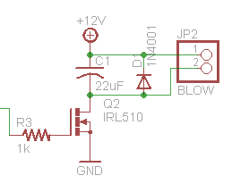
Note that I’ve changed from Bob’s design in that I use an IRL510 instead of an IRF510. The IRL is a 5V logic-level part and the IRF is a “standard” part, which it seems is 10V. This part might also be overspecced, considering it will pass 100V/5.6A and I only need 12V/180mA. If I were going to try to make these for profit, this would probably be something I’d try to save a little money on. I’d also try to figure out some way to save on labor, because I’ve probably spent at least 100 hours on the HeaterMeter so far. This circuit could use some other refinement too, I think I’m getting feedback right around the point where the fan turns on that sometimes causes corruption in the LCD display. That’s not a good sign.
Something that took me a long time to find an answer on was the diode across the fan leads. I couldn’t figure out what it was there for, and it appeared to be in backward in other schematics if it was supposed to be there to prevent the 12V line from being hooked up backward. This is called the freewheeling, snubber, supressor, or flyback diode. When an inductive load, such as a fan or relay is hooked to a MOSFET or any switched power, you should include such a diode. Fans and relays are coils, so the current going through them sort of has momentum. When you switch the current off, it wants to keep flowing. The problem is that the silicon switch in the MOSFET is preventing that from happening, so what happens is that the coil builds up a large reverse voltage. In some cases up to 100x the incoming voltage. This can arc and fry a silicon switch, do bad things to batteries, or burn contacts in physical switches. The diode makes the current loop around until it dissipates, and will generate a reverse voltage roughly equal to the forward voltage of the diode (if my reading is accurate). A 1N4001, which will stop up to 50V, should be sufficient for this application but any 1N400x should work.
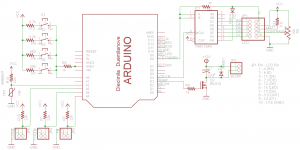
Here is my overall v3 schematic for the Arduino BBQ Grill Controler project codename HeaterMeter. I actually built a v2 schematic in the construction post that will follow this, but I am slowly morphing it to a v4 for reasons I will later describe. The file is an EAGLE 5.0 schematic and board layout file. I think I’ve got everything needed to view it, but I’ve never distributed a schematic so you may have just downloaded 43kB of useless 1s and 0s.
HeaterMeter Schematic v3
Comments are closed.


