Things Learned as a Frequent Typist
Adding backlight control to Waveshare 7″ touchscreen
I can’t say enough good things about OctoPrint. I can control either of my printers from any computer in my house, starting prints, aborting prints, uploading gcode or slicing, visualizing and the logo is quite endearing as well. With the addition of plugins, the web UI took a leap forward when BillyBlaze wrote TouchUI which adds a simpler finger-friendly interface that works well on tablets and phones. Being able to abort a print and restart it from an old Nexus 7 2012 tablet without having to fire up a computer really saved me a lot of trips back and forth. The Nexus tablet does an OK job, but it always chugs for a while when first woken up– something that doesn’t help when you’re quickly trying to stop a print that is in catastrophic failure mode. Recently a 7″ LCD panel came into my possession for use doing development to replace an old 24″ display that was taking far too much space on my desk just to be a temporary head of an embedded Linux system and I hooked it up to a Raspberry Pi to try it out running the TouchUI locally against OctoPrint.
The test went so well I went out searching for LCD touchscreens for my C-Bot 3D printer named Prontwoer. I didn’t want to have to run a special Linux distro just for the touch to work, and I found a Waveshare 7 inch IPS LCD with capacitive touchscreen which worked as a HID device and was therefore natively supported by my Raspbian install. In addition to the HDMI port, there is a microusb port that both provides power to the display and sends back the touch data. I was dubious of this configuration, as my 7″ development display pulled 12V ~300mA or 650mA when powered at 5V. It seemed like a lot to pull from the Pi USB port but assumed I’d be able to mod the board to take 12V to drive it.
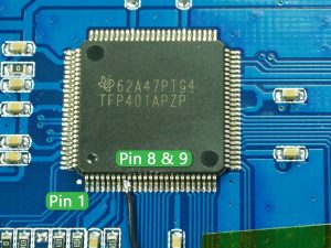
- Texas Instruments TFP401x PanelBus Digital Receiver – HDMI decoder/panel driver
- Texas Instruments TPS6104x Boost Converter – Positive and Negative LCD bias voltage (labeled PHOI)
- PowTech PT4103 White LED Step-Up Converter – Constant current backlight driver (labeled 4103)
- Atmel EEPROM – Assume for EDID storage
- 5V USB powers an LM1117-33 which provides the 3.3V rail
The TPS6104x and PT4103 boost chips operate at an absolute maximum 6V so my plans of rigging an extra 12V supply to it for power were dashed, short of lifting the microusb land for +5V and strapping my own 5V step-down to the display. The bigger disappointment came when the DPMS display blank kicked on and the display turned black, but the backlight stayed on. I have hdmi_blanking=1 in my config.txt which allows my development display to sleep with the backlight off and I thought this would be standard across all displays. The Waveshare display has a physical switch on the back to turn off the backlight. That’s an OK feature but I’d rather have it behave like a monitor would, going to sleep after a period of inactivity and springing back to life the instant I touch the display instead of having to feel around on the back for a small switch.
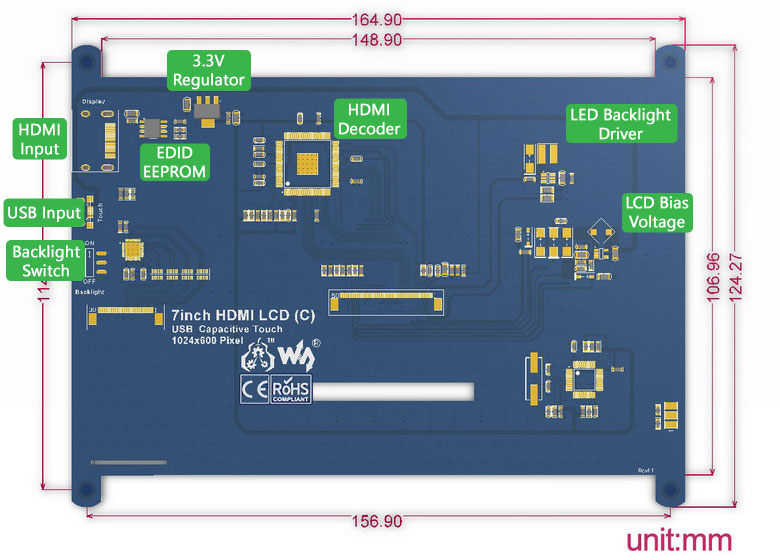
Location of the components on the Waveshare LCD driver board.
Some looking into a way to detect that there is no signal directly on the HDMI lines wasn’t turning up any easy answers, the circuit seemed to have to be pretty complicated and snoop the signals. I started getting pretty mad at TI, expecting that clearly they didn’t have this function or surely Waveshare would have used it. Reading the TFP401x datasheet filled me with hope as I found the SCDT (sync detect) pin. This goes low when there hasn’t been an HDMI clock signal for 1 million cycles. The datasheet even recommends tying it to the !PDO (power drive output enable) pin to shut down the driver when there is no output. Close inspection of the display PCB looked like these two pins were disconnected, or at least connected under the QFP. Multimeter testing also showed SCDT had 3.3V when there was an HDMI signal, 0V when there wasn’t.
I had my drive signal, now I just needed to figure out how to use it to disable the backlight. First instinct was to replace the switch with a MOSFET and be done. Looking over the board in greater detail, the 5V USB comes in and goes under the board, down to the switch, and the switched output goes back under the board and pops up by the PT4103. The PT4103 has an enable pin which can be PWMed to change the display brightness, but in this design, the pin is pulled up to the input voltage by the 10k (103) resistor right by the chip. The datasheet tells us that the enable high minimum voltage is 1.5V, so our 3.3V signal should be enough to drive this and provide the 1uA drive current.

Time for action, all that needs to be done is
- Remove the 10k pullup resistor from the PT4103
- Solder one end of a wire to the new new exposed foodprint from the pullup resistor. Be sure to connect to the enable pin side, not the 5V input side!
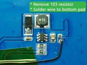
- Run a wire from SCDT pin 8 of the HDMI chip to the enable pin of the LED driver.
- To make soldering easier and provide further power reduction benefit, solder the wire to both pin 8 and !PDO pin 9. The pins on the HDMI chip are 0.27mm so they are hard to solder onto. I just placed a 30AWG solid core wire between these two pins and touched the soldering iron to it and it fused the three together, giving me a nice 0.77mm target area.


5V power usage INCLUDING Raspberry Pi 3 with Wifi enabled
- On idle/display on: 875mA
- On load/display on: 1100mA max
- On idle/display off: 390mA
- Extra note: The LED driver is set to run at ~156mA, which seems pretty high. This can be reduced by replacing the two parallel resistors (1R0, 2R0) just below the PT4103 chip with a higher value.
It is worth noting that with this modification, it takes a second or two for the display to come on at first power up. This might be reduced by only linking pin 8 to the LED driver enable and leaving pin 9 untouched? The downside being that the drivers will remain active and consume more power. I’m quite pleased with the way it is currently though, and waking the display from sleep is near-instantaneous.
Comments are closed.